Ferrite, Balun and transformer EHT
Wandering around the net I've read the proposal for the use of ferrites recovered from transformers EHT (Extra Hight Tension) of televisions to make Balun.
The opinions about the use of these ferrites were not uniform but sufficiently intriguing.
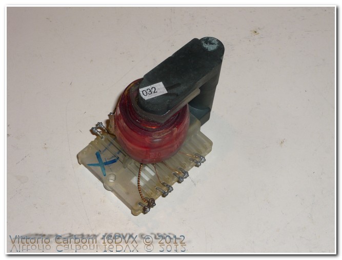
Intrigued by the idea so I've got a group EHT disassembling an old frame of a TVC Grundig. The transformer with its windings as it appeared in the first picture.
With a lot of patience, we proceeded to remove the windings. This can be done in different ways: with a drill Dremel accompanied by an abrasive disc, or with a saw cutting into the edge of the windings. Please note: The ferrite core is incredibly hard but ... fragile, therefore work with the greatest care in removing the windings.
Complete the work this is what you get.
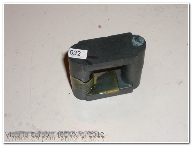
The physical dimensions of the core are derived as follows:
-diameter cylindrical columns: about 15 mm-height: about 49 mm.
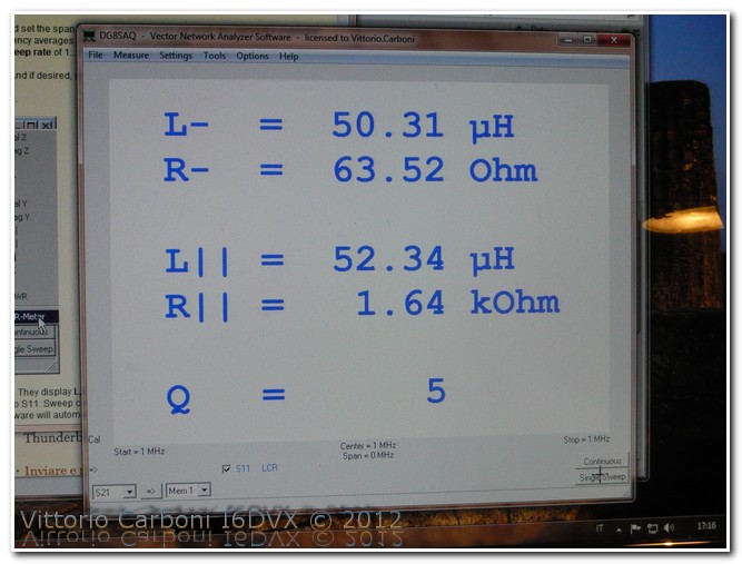
To get an idea, at least comparative, the permeability of the ferrite that composes the core, have been wrapped 10 turns on a column and has measured the value of inductance of the winding made, the measurement was performed with LC Meter [i] to few kilohertz obtaining values of about 54uH.
The same measurement was also performed with the VNWA2, at a frequency of 1MHz, obtaining values comparable with those measured previously.
The windings, to achieve a balun with a 4:1 ratio, are made with flat red-black from 2 x 0.50 mm for the windings 6 and 9 turns.
In the case of 10 and 12 turns has opted for smaller conductors, so as to retract the winding space available (about 32 mm) column.
The scheme used is as follows, it is important that the windings on the two columns have opposite directions.
Following the photos of the ferrite with the windings 6 and 9 turns and 10 turns.
The frequency range involved in the measurement was chosen in the range 1 MHz - 81 MHz, in order to verify the possibility of using 160 m as well as study the behavior of more than 6 m.
The results of measurements have been reported, for convenience of reading, in a single graph. Were placed markers to amateur radio frequencies.
http://www.i6dvx.it/en/lavori-in-corso/ferriti-e-balun.html#sigProId855b431648
http://www.i6dvx.it/en/lavori-in-corso/ferriti-e-balun.html#sigProId9945b5d4fb
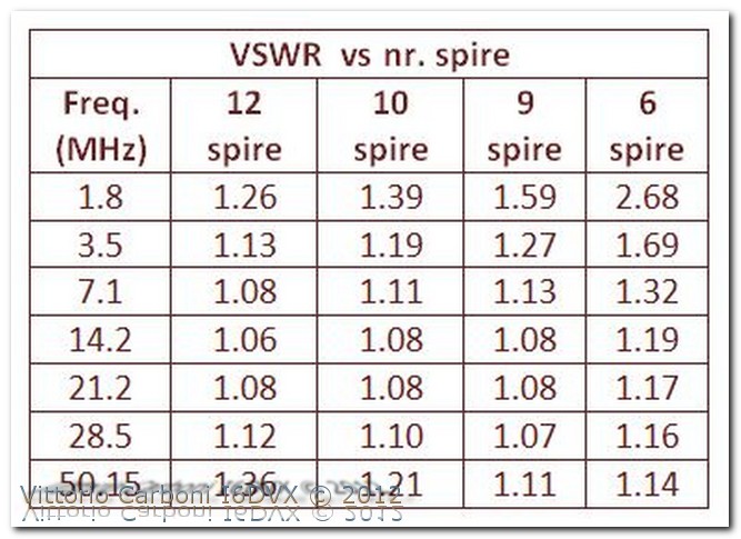
The black color is related to the winding of 6 turns, the color orange in 9 turns, 10 turns purple to green and finally to 12 turns. In abscissa there is the frequency (1 MHz-81 MHz), in the ordinate the value of VSWR, and the grid shows intervals of 0.2, starting from 1 up to 3 of VSWR. For ease of reading, has been transcribed to the following table, from the data reported in the readings of the markers of the previous graph. The table shows the values of VSWR at different frequencies for windings with a different number of turns.
Conclusion
The answer to the question if it were possible to use such ferrite for the realization of Balun is substantially positive. It can be interesting to make some evaluations on the number of turns as a function of frequency in which the Balun has to work. We note that it is recommended to use an extended frequency range as well, no combination of turns / frequency generated results. It is therefore a trade-off: if the balun should be used for high frequencies, say from 40 m to 6 m, probably the solution with 6 turns is the best. Offers an answer almost flat from 7 MHz to over 80 MHz If we are interested to operate on lower frequencies, starting for example from 3.5 MHz, the best solution seems to be the one with 10 turns, which I personally prefer.
In carrying out the windings for the measures was not asked due care in selecting the section of the conductor and the insulation, which is rather appropriate under construction final.
Lacking the specifications of ferrite is difficult to estimate the value of the maximum power deliverable. Considering the physical size it is considered to be able to 'manage' at least 100-200 W PEP on SSB.
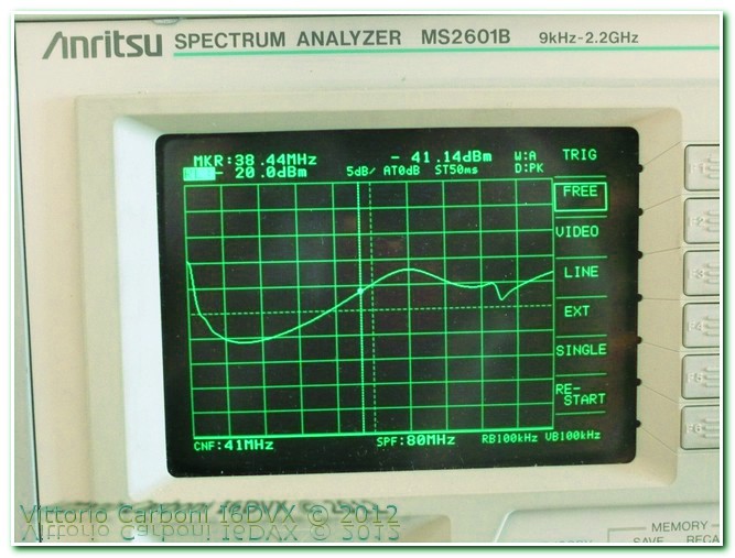
The measurements reported herein were carried out after calibration of the instruments, and to validate the accuracy, have been carried out, on the configuration with 10 turns, measures both with the VNWA, both with spectrum analyzer and directional coupler.
The data read by the spectrum analyzer have been corrected taking into account of the attenuation of withdrawal of the directional coupler, from processed in dB Return Loss (RL) in VSWR with the following formula:
VSWR = (1+(10^RL/20))/((10^RL/20)-1) [ii]
The result was placed on a graph, for comparison with the values obtained with the measurement via the VNWA2, for a limited frequency range upward to 60 MHz.
http://www.i6dvx.it/en/lavori-in-corso/ferriti-e-balun.html#sigProId95b81a2875
It can be seen as an instrument error is present and inevitable, but of extremely contained entity to confirm the accuracy of the measurements.
For a more rigorous and comprehensive on Balun, I recommend consulting the excellent work of Lucio, IW2FND [iii].
73 de I6DVX
Related Topics
Pubblicazions: Ferriti e Balun, articolo in PDF


