")

Tone Oscillator
At the Section A.R.I. Senigallia we started a course in telegraphy. Now abolished the examination requirements in proving knowledge of the CW to get the license of radio operator, the course is aimed at those who, abandoned or telegraphy after passing the exam, or who never have approached to the code Morse instead now show interest in this way of communicating.
Obviously after the retrieval of a telegraph key, it is presented the need for a tone oscillator that produces the note. After a quick search on the Internet, the first copy made consisted of an audio oscillator obtained with an integrated, NE555 in astable multivibrator configuration. Although endowed with the ability to adjust the frequency of the generated note, immediately several 'students' signaled the unpleasantness of the note. The circuit is in fact a square wave generator without any output filter, thus very far from a known 'pure'.
Considering the already significant commitment ear during the course has bounced into the net looking for some oscillator scheme but this time not square wave but sine wave. The choice fell on a type of oscillator called T-Twin, where the feedback network, which determines the frequency of operation, is realized with three capacitors and three resistors. This type of oscillator generates a wave with very low distortion. The active element is a transistor, a second transistor is used as a separator, which follows a small low frequency amplifier, realized with an integrated circuit type LM386, so as to directly drive a loudspeaker. The pattern is visible in the following figure.
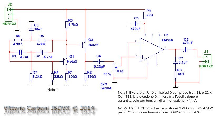
Starting from the scheme have made two different circuit boards: the first called v6 with all the traditional components of type True Hole (hole). The second type called v5 mixed technology: all the classic passive components through hole, chip and the transistors in SMD. The motivation for the latter choice is to be found on one side to allow to approach to the modern technologies in surface mounting, with a simple construction, while maintaining, with the use of traditional components of much more generous size than equivalent Smd, a relative ease in the routing of the single-sided printed circuit. When installing the v5 version stagnate pitches beforehand who will welcome the SMD components, then carefully place components and solder simply placing the soldering iron tip, slightly wet pond on the pin to be welded. Pay attention to the orientation of the chip. Most picky pay attention to Note 1 shown on the diagram. By adjusting the value of the resistor R4 can easily go down to the lower distortion coefficients to one per cent (4..6 per thousand). I recommend starting with a value of 20 kilohms. At worst distortion is kept within 3%. Putting in parallel with another resistor R4 (180 .. 330 kohms) the distortion decreases. Please note that below certain values of R4 the oscillation is turned off! With R10 you can to adjust the volume to an optimum level without exceeding not to increase distortion. The speaker is connected to J1, power, 12 VDC of J2, polarity.
By way of mere curiosity, it was observed the spectrum, via SpectrumLab, of the generated signal, from both the first tone oscillator square wave, both of the successive prototypes v5 realized.
Any comment about it is superfluous. good construction
Download Schematic, Bill of materials, PCB - PDF, PCB - Gerber, Drill ecc.
-
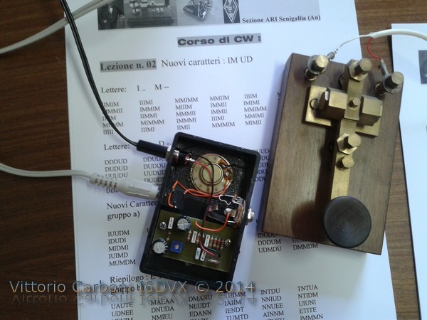
 Boxed prototipe
Boxed prototipe
Boxed prototipe
-
Wiring example
Wiring example
-
Signal output
Signal output
-
PCB solder side
PCB solder side
-
Master PCB v5
Master PCB v5
-
Schematic diagram
Schematic diagram
-
Silkscreen
Silkscreen
-
Spectrum: T-Twin oscillator #0
Spectrum: T-Twin oscillator #0
-
Spectrum: T-Twin oscillator #1
Spectrum: T-Twin oscillator #1
-
Spectrum: T-Twin oscillator #2
Spectrum: T-Twin oscillator #2
-
Spectrum: T-Twin oscillator #3
Spectrum: T-Twin oscillator #3
-
Spectrum: square wave oscillator
Spectrum: square wave oscillator
-
Tone oscillator
Tone oscillator


http://www.i6dvx.it/en/lavori-in-corso/tone-oscillator.html#sigProIdac96dc5df7