")


9 MHz I.F. Module
The design and construction of the intermediate frequency amplifier dates back to 2009. As center frequency we have chosen the value of 9 MHz, and all the architecture follows the trace of the famous project CDG2000 and everything detectable online regarding this matter. I've never published anything on paper, but I am going now to publish on the Internet, believing that any good idea can also be used by other lovers of self-construction.
The whole chain of intermediate frequency is based on amplifier Analog Devices AD603. Here is a block diagram of the four amplifiers used in the IF2009, highlighting with the sophisticated AGC controler:
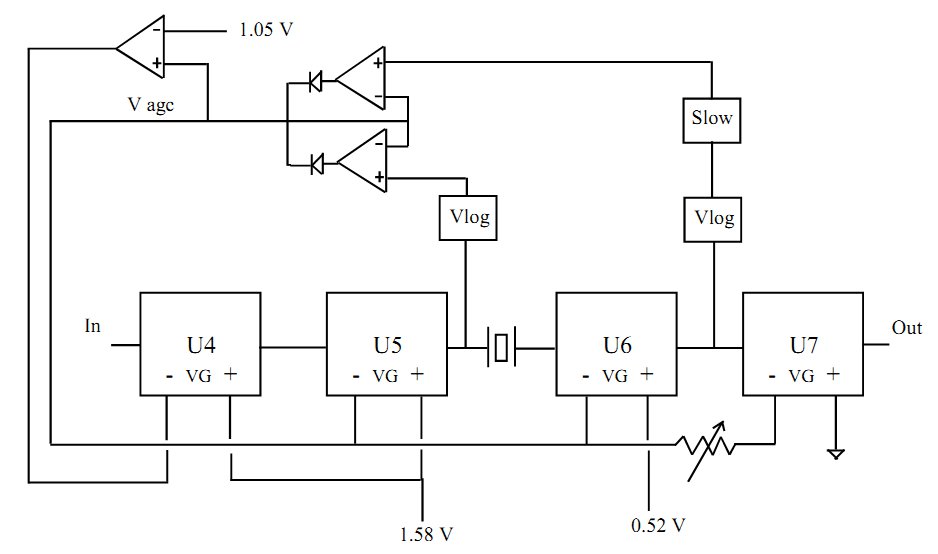
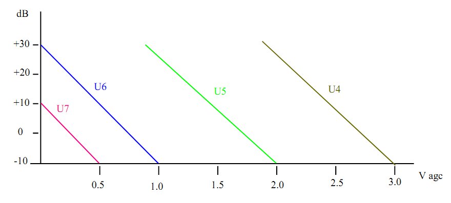
The AGC voltage operates progressively on the amplification chain. Each AD603 has a dynamic of 40 dB, in the range -10 dB 30 dB. The amplification / attenuation of the single integrated circuit according to the AGC voltage is in the chart below. Notice how the AGC voltage varies from 0 to 3 V; for lower voltage the gain of the amplifier is reduced in the last stage, U7. Then the gain reduction occurs on the penultimate amplifier, U6,and then moves to U5 and eventually to U4. In this way, the overall dynamics of the chain of amplifiers is greatly increased.
For convenience of readers the whole diagram has been divided into 4 sheets which are attached as PDF files to this article. The circuit is mounted on a double-sided PCB with the following layout.
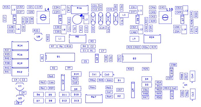
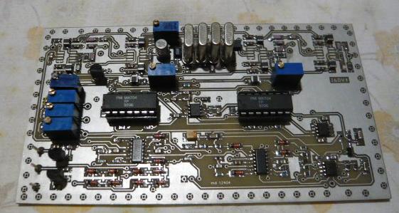
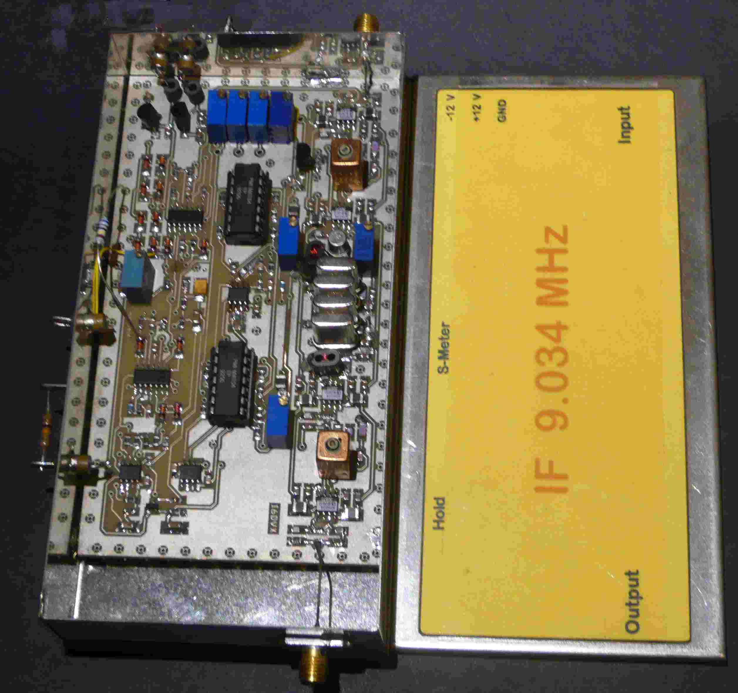
The picture shows the prototype during assembly. instead the next image shows the prototype mounted and boxed. For calibration refer to the CDG documentation 2000.
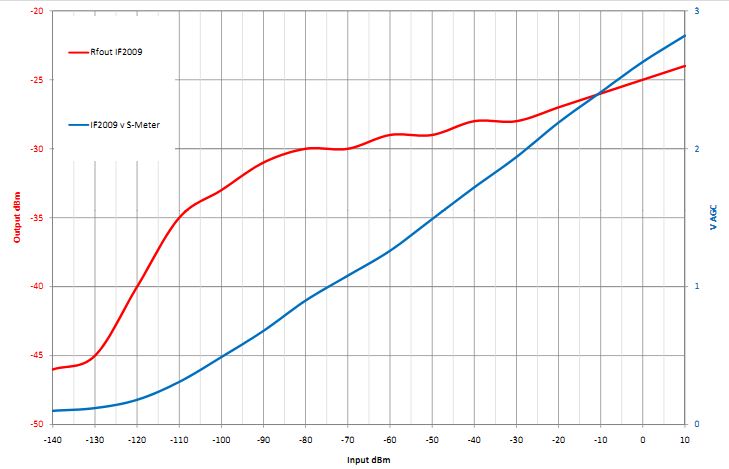
The chart below shows the transfer characteristic Vout = f (Vin) and the value of the voltage SMeter (AGC) as a function of Vin.
Argomenti correlati
Schematic: IF Part 1
Schematic: IF Part 2
Schematic: AGC Part 1
Schematic: AGC Part 2